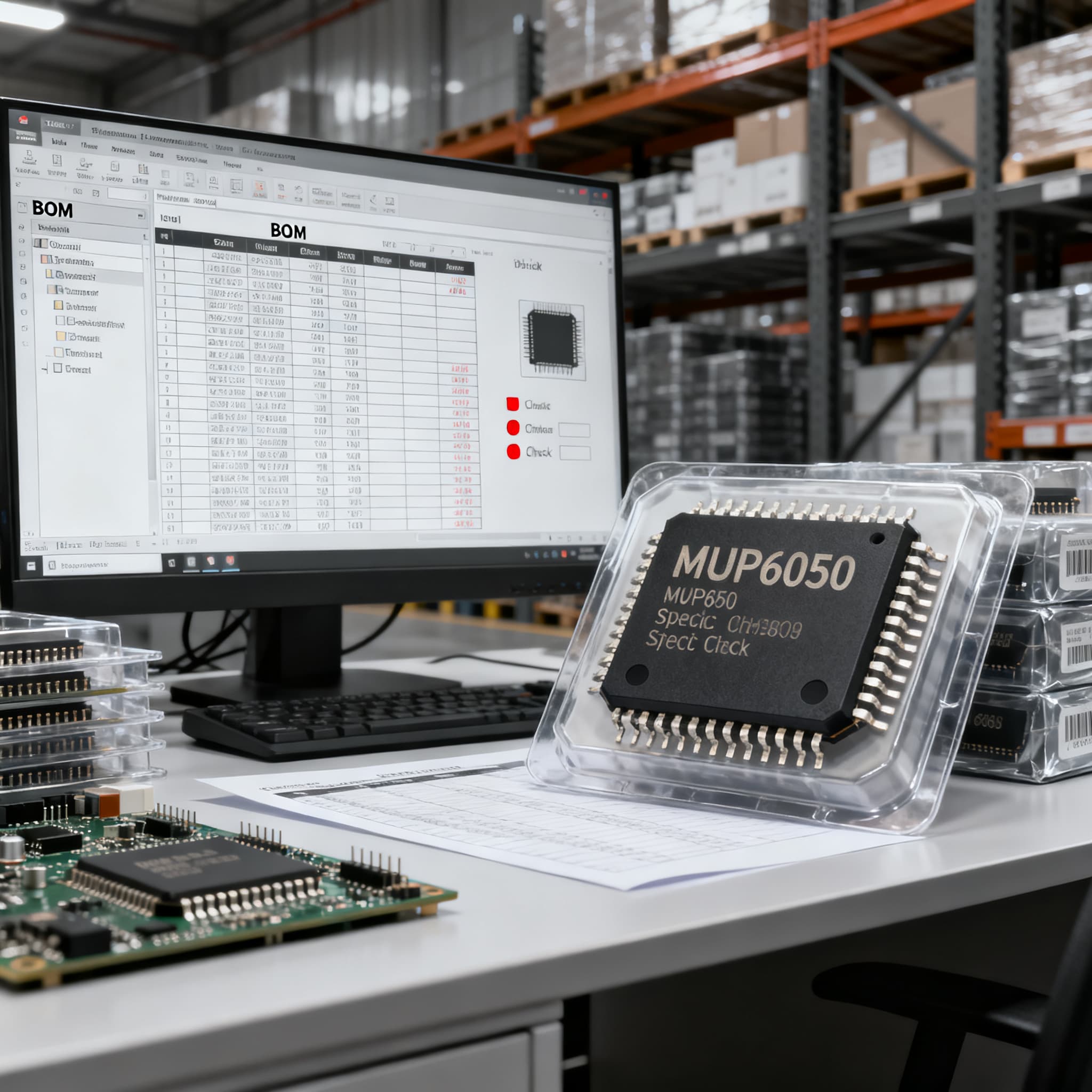
MPU6050 Procurement Guide: Pinout and Spec Checks for RFQ
MPU6050 procurement checklist: datasheet specs and pinout fields to verify on RFQ, plus BOM upload path on BOMNow.
MPU6050 Procurement Guide: Critical Pinout and Spec Checks for RFQ Success
The MPU6050 Is Full Obsolete—Here’s What That Means for Your BOM Risk
The MPU6050 isn’t just “not recommended for new designs.” TDK InvenSense now lists the MPU-6050 as obsolete—a full end-of-life status, not NRND—as confirmed by PCBWiki and the TDK Product Center lifecycle page. For procurement teams, this changes everything. Remaining loose-chip supply is dominated by third-party sellers, with a high percentage of remarked, relabeled, or outright counterfeit parts. If your BOM still carries the MPU6050, you’re carrying a single-source risk that can derail production without warning.
Understanding the typical trajectory from NRND to final shipment helps quantify the exposure. NRND status triggers a Product Change Notification (PCN) and a formal last-time buy announcement, followed by a final order window—often 6–12 months—and a final shipment date. Industrial Monitor Direct documents this sequence clearly. Meanwhile, TT Electronics’ lifecycle data guide explains how YTEOL estimates are reviewed annually, giving buyers a maximum five-year horizon. For the MPU6050, those windows have already closed. Any order you place today will draw from residual open-market stock, not from authorized distribution.
This isn’t a shortage that will ease. It’s a permanent supply vacuum. Buyer behavior must shift from “find me reels” to “find me a verified, authentic batch, and let’s get an alternate qualified before this line goes cold.” The sections that follow arm you with the pinout checks, parametric verification points, and alternative evaluation criteria you’ll need to de-risk every RFQ and keep your lines running.
MPU6050 Pinout and Parametric Checks Every RFQ Should Include
Before you cut a purchase order for any lot of MPU6050 chips—especially from non-franchised sources—your RFQ must demand a minimum set of electrical and mechanical verification data. Start with the official MPU-6000/MPU-6050 Product Specification Revision 3.1 (CDIWeb), also mirrored by Mikroe, Alldatasheet, and Scribd. Cross-reference the key pin functions below to ensure the parts match the genuine QFN-24 footprint.
| Parameter / Pin | Genuine MPU6050 Value | RFQ Verification Notes |
|---|---|---|
| VDD supply voltage | 2.375 – 3.46 V | Absolute max 6 V; prolonged exposure to 6V may affect reliability. Confirm regulator output on board. |
| VLOGIC reference | 1.71 V to VDD | Sets I²C logic level; must be ≤ VDD. Floating VLOGIC may cause intermittent I²C failures. |
| I²C address select (AD0) | 0x68 (AD0 low), 0x69 (AD0 high) | Ask supplier to confirm default address strapping matches your board layout. |
| Accelerometer full-scale range | ±2 g / ±4 g / ±8 g / ±16 g | Verify register configuration; clone parts may report spurious values at ±8 g and above. |
| Gyroscope full-scale range | ±250 / ±500 / ±1000 / ±2000 °/s | Self-test response limits per Rev D (date code 1147+) must be within ±20% of nominal factory trim. |
| I²C clock stretching & DMP | Supports DMP (Digital Motion Processor) | Counterfeit chips often have broken DMP or absent FIFO; insist on a DMP readout test over 1000 samples. |
| Package & marking | QFN-24 (4×4×0.9 mm), marking per Section 11.6 | Use visual guide from datasheet: top mark 1st line “MPU-6050”, 2nd line date code (YYWW) + lot traceability. |
Tip: If you’re sourcing integrated modules rather than the bare IC—such as the popular GY-521—Components101 details the breakout pinout differences (VCC, GND, SCL, SDA, XDA, XCL, AD0, INT). However, module-level sourcing carries its own headaches (see FAQ below). For either form factor, include in the RFQ a clear requirement: “Self-test response must fall within the limits of the MPU-6000/MPU-6050 Product Specification Rev 3.1 for Revision D parts. Vendor to supply test report for a statistically valid sample.”
Absolute maximum ratings and recommended operating conditions must appear side by side in your internal qualification checklist. I²C address conflicts, VLOGIC miswiring, and fake DMP are the three most common failure modes we see in field returns. Fixing them at incoming inspection is far cheaper than after SMT.
Alternatives to the MPU6050 for New Designs: A Procurement Comparison
TDK’s official replacement for the MPU-6050 is the ICM-42670-P, but it is not a drop-in. The pinout, package dimensions, and register map all differ; a board spin and firmware port are mandatory. Several other modern 6‑axis IMUs are frequently cited as upgrade paths: ICM20948, BMI270, BNO055, and the older MPU9250. Utmel and Bettlink offer head‑to‑head overviews, while WatElectronics and Components101 list equivalent modules. The table below compares the most relevant candidates against the original MPU6050.
| Metric | MPU6050 (obsolete) | ICM-42670-P (TDK recommended) | BMI270 (Bosch) | Selection Note & Failure Boundary |
|---|---|---|---|---|
| Accel range | ±2/4/8/16 g | ±2/4/8/16 g | ±2/4/8/16 g | Similar ranges; verify noise density at lowest g for your application. |
| Gyro range | ±250/500/1000/2000 °/s | ±250/500/1000/2000 °/s | ±125/250/500/1000/2000 °/s | BMI270 adds ±125 °/s for high-res slow motion; useful in robotics. |
| Digital interface | I²C (400 kHz max) | I²C & SPI (24 MHz) | I²C & SPI | SPI can offload MCU faster; check if your MCU supports both. |
| Package | QFN-24 (4×4 mm) | LGA-14 (2.5×3 mm) | LGA-14 (2.5×3 mm) | No pin‑to‑pin compatibility; complete PCB redesign is universal. |
| Supply voltage | 2.375–3.46 V | 1.71–3.6 V | 1.71–3.6 V | Wider operating range simplifies 1.8 V rail designs. |
| On‑chip DMP / sensor fusion | Yes (DMP) | No DMP; basic FIFO | No DMP; configurable sensor fusion via Cortex-M0 host | If your firmware relied on DMP, expect to rewrite fusion algorithms. |
| Lifecycle status | Obsolete | Active (Production) | Active (Production) | Confirm latest PCN with franchised distributor before design lock. |
Key takeaway: None of these alternatives is a true drop-in. The ICM-42670-P is the manufacturer-endorsed path, but the BMI270 often wins on power consumption in wearables. The BNO055 (Bosch) adds an on‑board cortex-M0 running BSX 3.0 fusion, but typically operates at 3.3 V and a different I²C register map. Bettlink’s list includes the ICM20948, which adds a magnetometer (9‑axis), making it a suitable upgrade if you need absolute orientation. Every migration requires PCB layout changes, firmware rework, and full qualification. Plan for at least an 8–12 week design-in window, and secure silicon early: the IMU market remains tight.
How to Authenticate MPU6050 Stock and Qualify Substitutes Without Delaying Production
Stopping a production line isn’t an option, but neither is installing counterfeit MEMS sensors that pass initial power-on and fail in the field six months later. A layered authentication process, starting with documentation and ending with destructive analysis only when necessary, keeps your lines moving while controlling risk.
| Action | When to Use | Trade‑off |
|---|---|---|
| Request PCN & last‑time buy records from franchised sources | Before any open‑market purchase | Confirms official lifecycle; may reveal that no authorized stock remains, forcing redesign. |
| Visual marking inspection per datasheet Section 11.6 | Every incoming lot (100% sample for low volume; AQL sample for high volume) | Catches gross laser etching anomalies; won’t detect professionally remarked units. |
| In‑circuit self‑test routine vs. Rev D limits | Every batch, on a sample of ≥50 pcs | Requires a test fixture with known mechanical stimulus; deviations >20% from nominal Self-Test Response indicate clones. |
| X‑ray or decapsulation of suspect units | When self‑test fails or visual marks are suspicious on >5% of lot | Destructive; costly; only for high‑volume validation or when legal traceability demands evidence. |
| Tear‑down of GY‑521 modules to verify die | Before qualifying a module supplier for production | Destroys module; compare die marking against known genuine TDK patterns; often reveals clone dies. |
| Initiate multi‑source qualification for a live alternate (ICM-42670-P, BMI270) | Immediately, while existing stock is still available to compare | Engineers must divert time to layout and firmware; delay risks line stoppage after stock depletion. |
Start with documentation. Authorized distributors and the manufacturer’s PCN archive (see the NRND/EOL guide) are your first line of defense. If the seller can’t provide a traceable chain back to TDK InvenSense, treat the lot as high risk regardless of date code. For chips already on your shelf, run the self-test protocol defined in the MPU-6050 datasheet revision 3.1. Self-test response values outside the ±20% window are the quickest, cheapest red flag.
For any MPU6050 still going into production, lifecycle monitoring data can help you model the remaining useful life of your stockpile, but it can’t extend supply. The strongest procurement move you can make today is to start the re-design before the last reel is consumed. Build a qualification plan that tests at least two active‑status alternatives in parallel, so you’re never locked into another sole‑source crisis.
MPU6050 Sourcing: Questions Our Industrial Procurement Readers Ask
Q: Is the MPU-6050 still available from franchised distributors, or is it only found on the grey market?Authorized stock is depleted. TDK’s product page confirms obsolete status, and franchised distributors have zero inventory. Any loose chips you find originate from third-party sellers, brokers, or excess‑inventory aggregators. Even if date codes appear recent, treat every shipment as high‑risk. Insist on a full traceability report and a statistically significant self‑test sample before accepting the material.
Q: How do I verify that an incoming batch of MPU6050s isn’t remarked or counterfeit?Cross‑check package markings against the official datasheet Section 11.6 layout: top mark line 1 “MPU-6050”, line 2 date code (YYWW) and lot identifier. Run the self‑test routine and compare the output to the Revision D limits. For larger volumes or inconsistent results, X‑ray inspection can reveal die size discrepancies, and decapsulation can expose a non‑TDK internal layout. At minimum, a 50‑piece random sample must pass the self‑test before the lot enters your stock.
Q: What is the recommended alternate according to TDK, and is it a true drop-in?TDK lists the ICM-42670-P as the replacement. It is not a drop‑in: the package (LGA-14 vs QFN-24), pinout, supply voltage range, and register map are all different. A complete PCB redesign and firmware port are required. If your product roadmap can absorb that effort, the ICM‑42670‑P offers lower noise and wider VDD range, but you must treat it as a new design‑in.
Q: Are there any pin-compatible alternatives that work without PCB changes?No. No true pin‑compatible direct replacement exists for the MPU6050 QFN‑24 footprint. Modules like the GY‑521 incorporate the MPU6050 chip, but they are breakout boards, not solderable ICs. For new PCB layouts, you can consider the ICM‑20948 (9‑axis) or the BMI270 (6‑axis), but both require layout changes and firmware adaptation. Don’t let a supplier sell you a “fully compatible” chip without your engineering team verifying at the Gerber level.
Q: For legacy products, is a last-time buy still feasible, and what are the typical timeline windows?Since the MPU-6050 is already obsolete, the official last‑time buy window from TDK has closed. You may find residual stock through independent distributors, but quantities are unpredictable and authenticity cannot be assured without the checks described above. If your product still has years of demand ahead, start a redesign immediately and use any remaining genuine stock only as a bridge. The “last time buy” for you now is whatever you can validate right now—there is no next opportunity.
Q: Should I rely on MPU6050 modules (GY-521) for production, or are they only for prototyping?GY‑521 modules are prototyping aids. The on‑board MPU6050 chip is often a clone, and module‑to‑module variance in regulator performance, pull‑up resistors, and sensor orientation makes them unsuitable for production without full qualification. If you must use them in small‑batch manufacturing, tear down a sample to verify the die, and lock the module supplier with an agreed‑upon incoming inspection spec. For any volume, design around a live, active IMU so you aren’t dependent on a cottage industry of breakout board inventories that could vanish overnight.
References & Further Reading
- MPU-6050 Datasheet, Footprint & Pinout – PCBWiki
- TDK Product Center – Product Status Information
- Understanding ‘Not Recommended for New Designs’ – Industrial Monitor Direct
- Instant Access to Life Cycle and Obsolete Product Data – TT Electronics
- MPU-6000 and MPU-6050 Product Specification Revision 3.1 – CDIWeb
- MPU-6050 Datasheet – Mikroe
- MPU-6050 Datasheet PDF – Alldatasheet
- Datasheet MPU6050 – Scribd
- MPU6050 Module Pinout, Configuration, Features – Components101
- MPU6050 Module: Datasheet, Alternative, Comparison – Utmel
- 7 Best MPU6050 Alternatives for New Designs – Bettlink
- MPU6050 Module : PinOut, Datasheet, Equivalent & Its Working – WatElectronics
The MPU6050’s obsolete status forces an uncomfortable transition, but it also creates an opportunity to redesign with a modern IMU that offers better noise performance, a wider supply range, and guaranteed long‑term availability. Whether you’re clearing the last reels from a legacy build or launching a new product, every RFQ must now include explicit authenticity clauses, self‑test verification, and a migration timeline. Don’t let a single obsolete MEMS sensor hold your BOM hostage.
Ready to consolidate your sourcing effort? Upload Your BOM for a single consolidated quote, or Request a Quote for the MPU6050 and we’ll help you evaluate remaining stock authenticity while you plan the cut‑in of a sustainable alternative.