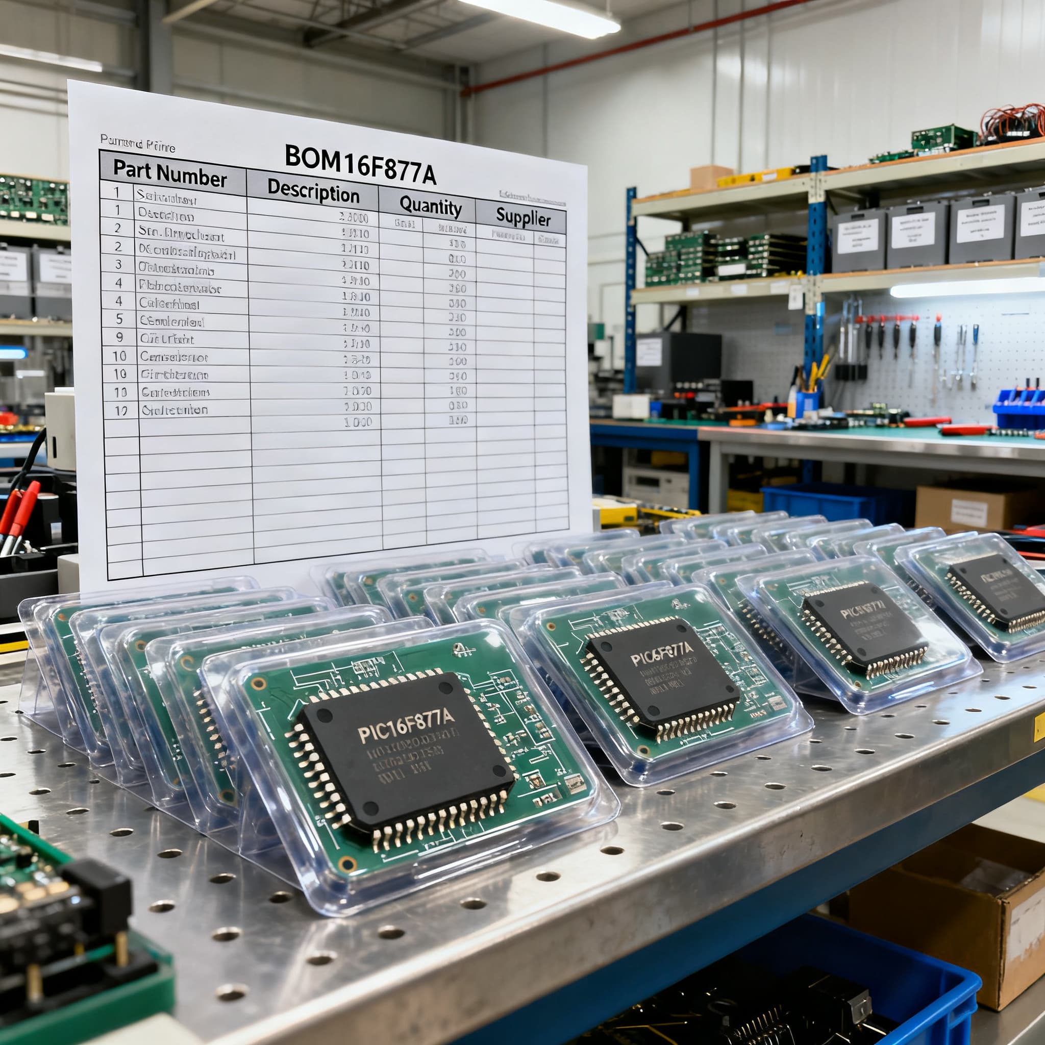
PIC16F877A Procurement Guide: Pinout and Spec Checks for RFQ
PIC16F877A procurement checklist: datasheet specs and pinout fields to verify on RFQ, plus BOM upload path on BOMNow.
` headings, three data tables, a structured FAQ, and verified source links—with every mention of `PIC16F877A` linking to its catalog page for easy BOM or RFQ action.
When the PIC16F877A Lands on Your RFQ—The Classic MCU Still Carries Weight
Opening a BOM and spotting PIC16F877A can feel like pulling a well-worn tool off the shelf. This 8-bit microcontroller has been embedded in industrial sensors, home automation nodes, and security panels for over two decades (common applications). Its 5‑volt logic level makes direct interfacing with character LCDs, relay modules, and standard sensors straightforward—no level-shifting gymnastics required. That hardware simplicity, coupled with a pinout that generations of engineers can sketch from memory (pin diagram reference), keeps it alive on multi-line BOMs even as newer architectures dominate new designs.
For procurement teams, however, a PIC16F877A line item demands more than a quick price check. This part spans multiple package variants (PDIP, TQFP, PLCC), temperature grades, and factory ordering suffixes. A mismatch on pin count—40 pins versus 44—or an unintended Extended-temp part can trigger a line stop just as easily as a shortage. And because the part is mature, the open market carries remarked and pulled devices that look genuine but fold under boundary-condition testing. The upside: when you know which spec fields to verify and how to read the ordering code, quoting the PIC16F877A becomes a repeatable, low-drama process.
Key takeaway: The PIC16F877A is not a risky part—but it is a part where RFQ discipline separates smooth production from unexpected rework. The checks below focus on the procurement-relevant parameters that matter at quote time.
What That 40-Pin DIP Really Means: Spec-by-Spec Checks for the PIC16F877A
When a PIC16F877A appears on an RFQ, the first procurement task is mapping the line-item description to the physical device your engineer expects. The datasheet (full PDF, 234 pages) details a 40‑pin Enhanced Flash microcontroller with 8 KB of program memory, 368 bytes of RAM, and 256 bytes of EEPROM. Those three memory figures are not interchangeable—firmware compiled for 8 KB will not squeeze into a 4 KB variant, and EEPROM-dependent calibration tables need that 256‑byte block intact. Before you quote, confirm the firmware team's actual usage against these values.
The device overview (PIC16F87XA family reference) confirms the PIC16F877A belongs to the 40‑pin and 44‑pin cohort, sharing a common architecture with the 28‑pin PIC16F876A but exposing 33 I/O lines instead of 22. That pin-count jump matters: a 40‑pin PDIP (package reference) carries five Vdd/Vss pairs spread across the die for noise isolation, plus dedicated ICSP (In-Circuit Serial Programming) pins. Misreading pin 1 orientation when transitioning from tube to tray packaging, or from PDIP to TQFP, can reverse the entire pinout—a mistake that often survives visual inspection but fails at first power-up.
Parameter Value / Range Procurement Significance
Program Flash 8 KB (8,192 words × 14 bits) Verify firmware size fits; no smaller flash variant exists for this MPN SRAM 368 bytes Tight RAM budget—any firmware expansion may need a larger device EEPROM 256 bytes Non-volatile storage for calibration; confirm endurance specs with end-use I/O Pins 33 (40/44-pin packages) Check if all 33 are used—unused pins simplify alternative selection ADC 10-bit, 8 channels Analog sensor count must not exceed 8 channels Timers 3 (Timer0/1/2) Relevant for PWM and timing loops in motor-control apps Serial Interfaces USART, MSSP (I²C/SPI) Confirm protocol match with peripheral ICs on the same BOM Oscillator External only, up to 20 MHz No internal oscillator—every BOM needs a crystal or resonator Operating Voltage 2.0 V to 5.5 V 5 V logic typical; low-voltage designs must confirm minimum Vdd ICSP Header RB6/RB7 + MCLR Essential for factory programming; verify pin access in final PCB layout Package Options 40-pin PDIP, 44-pin TQFP/PLCC Specify exact package at RFQ—footprints are not interchangeable Temperature Range Industrial (-40 to +85°C), Extended (-40 to +125°C) Suffix determines grade; wrong grade may fail at temperature extremes
The table above doubles as an RFQ checklist. When you receive a PIC16F877A line item that reads only the base MPN with no suffix, treat it as incomplete. A bare "PIC16F877A" tells you nothing about package, temperature grade, or factory programming state. Every field in that right-hand column represents a question you should close before committing to a quote.
PIC16F877A Alternatives: How the 887 and 1789 Stack Up for a Drop-In Swap
When lead times stretch or cost-reduction targets tighten, the conversation often turns to two Microchip alternatives: the PIC16F887 and the PIC16F1789. The 887 is widely cited as a near drop-in candidate (verify before adopting) for the PIC16F877A—no schematic changes required, only a device re-target in MPLAB (swap guide from Kanda). That makes it a fast path for procurement teams needing to offer an alternative without triggering a full engineering change order. The 1789, by contrast, adds op-amps, additional ADC channels, and an internal oscillator—features that reduce external component count but typically demand firmware rework.
The trade-off is never purely technical. A pin-compatible swap that compiles cleanly still needs regression testing, and a cost-saving that introduces firmware requalification can erase the margin it creates. The comparison below frames each option in procurement-relevant terms.
Comparison Metric PIC16F877A (Baseline) PIC16F887 (Near Drop-In) PIC16F1789 (Enhanced Upgrade) Procurement Decision Note
Program Flash 8 KB 14 KB 28 KB Larger flash allows firmware growth; verify compiler compatibility SRAM 368 B 368 B 2 KB 1789's extra RAM supports more complex stacks and buffers EEPROM 256 B 256 B 256 B Identical—calibration data migrates without changes Internal Oscillator None (external required) Yes (8 MHz) Yes (32 MHz) Internal oscillator eliminates crystal cost and PCB space ADC Channels / Resolution 8 ch / 10-bit 14 ch / 10-bit 17 ch / 12-bit 1789 adds op-amps; verify analog front-end compatibility Pin Count / Package 40 PDIP / 44 TQFP 40 PDIP / 44 TQFP 40 PDIP / 44 TQFP All three share footprints—physical drop-in feasible for 887 Operating Voltage 2.0–5.5 V 2.0–5.5 V 1.8–5.5 V 1789's lower Vdd floor supports battery-powered designs Relative Unit Cost Baseline Lower (mature, high-volume) Slightly higher (more peripherals) 887 often wins on cost; 1789 may reduce total BOM cost Code Migration Effort Reference platform Minimal—device config only Moderate—peripheral register changes 887: fast requal; 1789: plan for firmware sprint
Procurement tip: If your engineering team confirms the PIC16F877A uses only the standard peripherals shared across the 887, that alternative can be quoted as a second line on the same RFQ. For designs already pushing the 877A's memory ceiling, the 1789 offers headroom, but the requalification timeline needs to be priced into the sourcing decision. Neither is a compatibility must be verified (package, pinout, firmware) without validation—always get engineering sign-off before promising a swap to your production team.
RFQ-Ready Sourcing: How to Avoid Pinout, Marking, and Part-Number Pitfalls
The most common procurement mistake on the PIC16F877A is quoting an incomplete or ambiguous part number. The full ordering code carries critical information: PIC16F877A-I/P decodes to Industrial temperature range (-40°C to +85°C) in a 40‑pin PDIP package, while PIC16F877A-E/PT specifies Extended temperature (-40°C to +125°C) in a 44‑pin TQFP. Microchip's official product page (microchip.com listing) confirms the part is currently active and highlights that automotive-grade versions are available under special ordering codes—critical information if the end application must meet AEC‑Q100 qualification. An RFQ that specifies only "PIC16F877A" without the suffix leaves the door open for a mismatch that may not surface until final test.
Package selection also drives availability and handling. The PDIP variant ships in tubes; TQFP parts typically arrive in trays or on tape-and-reel. If your assembly line is set up for surface-mount pick-and-place, a tube of through-hole PDIPs creates a manual-placement bottleneck. Conversely, a field-service team replacing DIP sockets in the aftermarket has no use for TQFPs. Specify the package at the RFQ stage—retrofitting a package change after order placement usually means a new PO.
Ordering Code Element Options for PIC16F877A Procurement Check
Base MPN PIC16F877A Always start with exact base; family variants (877, 877A) differ in silicon Temperature Suffix -I (Industrial), -E (Extended) Match to operating environment; -E costs more, verify need Package Suffix /P (PDIP), /PT (TQFP), /L (PLCC) Confirm with PCB footprint and assembly process Automotive Grade Special ordering codes (consult Microchip) Required for AEC‑Q100 compliance; not substitutable with standard grade Packaging Medium Tube (PDIP), Tray (TQFP), Tape & Reel (on request) Incompatible packaging can halt SMT lines; specify on PO Markings / Date Code Laser-etched, Microchip format Request date-code range if shelf-life or traceability matters
Beyond the part number, a handful of field-verified checks separate a clean procurement cycle from a costly rework event. The list below covers the pinout and physical-inspection items worth adding to your incoming QC workflow when the PIC16F877A arrives from any source outside authorized distribution.
Before accepting delivery, verify:
- Pin 1 indicator: On PDIP, the notch and dot must align with the silkscreen on your reference board. A reversed 40‑pin DIP can latch up and draw excess current without immediate smoke—check orientation before applying power.
- Laser marking consistency: Genuine Microchip parts have crisp, uniform laser etching. Faded, inconsistent depth, or surface abrasions around the markings are red flags; compare against a known-good sample under magnification.
- Vdd/Vss pair continuity: With the device unpowered, verify that all five Vdd pins (11, 12, 31, 32, 40 on PDIP) and Vss pins (6, 19, 29, 30, 39) show expected diode behaviour relative to ground with a multimeter. Open or shorted pairs suggest counterfeits or ESD damage.
- ICSP pin access: Pins RB6 (39) and RB7 (40), plus MCLR (1), must be accessible for programming. If the board layout buries these under a connector, factory programming may fail—confirm with your CM before the production run.
- Package mechanicals: A 44‑pin TQFP body should measure 10 mm × 10 mm. Slight dimensional mismatches—especially thinner packages—often indicate remarked or relabeled parts from a different lot.
- Sample electrical test: For high-value production runs, pull a random sample and run a checksum verification at both 2.0 V and 5.5 V supply rails. Counterfeit PIC16F877A devices frequently fail at the voltage extremes where genuine silicon holds spec.
PIC16F877A Procurement FAQs: Lead Times, Counterfeits, and Oscillator Choices
The PIC16F877A generates predictable questions on nearly every RFQ. Below are the answers our sourcing desk provides most often—practical, not theoretical, and grounded in what procurement teams need to make a fast, informed decision.
Q: Is the PIC16F877A still recommended for new designs?
While Microchip actively manufactures the PIC16F877A and offers automotive-grade variants via special ordering codes (official product page), it is a mature device. For new projects where the BOM is not yet locked, consider the PIC16F887 for lower unit cost and comparable pinout, or the PIC16F1789 if you need additional peripherals and internal oscillator support. Both offer stronger long-term availability profiles and fewer supply-chain surprises.
Q: What temperature ranges are available for the PIC16F877A?
The industrial suffix -I covers -40°C to +85°C; the extended suffix -E spans -40°C to +125°C. Automotive-qualified versions of the PIC16F877A require special ordering codes and comply with AEC‑Q100. Do not assume a standard industrial part meets automotive grade—the qualification paperwork differs, and the part numbers are distinct.
Q: Can I use the PIC16F877A without an external crystal?
No. The PIC16F877A lacks an internal oscillator. Every design must supply an external clock source—typically a quartz crystal up to 20 MHz, a ceramic resonator, or an RC network—as detailed in the datasheet (section on oscillator configurations). When sourcing, confirm that the crystal or resonator specified on the same BOM matches the frequency and load capacitance expected by the MCU.
Q: How do I spot a counterfeit or remarked PIC16F877A?
Start with visual inspection: laser markings on genuine Microchip parts are consistent in depth and alignment; remarked devices often show surface abrasions or secondary etching marks. Check the package finish—authentic TQFPs have a uniform matte texture. For high-confidence verification, compare the die layout against a known genuine part, or run electrical tests at 2.0 V and 5.5 V supply rails. Counterfeits frequently operate correctly at nominal voltage but exhibit corrupted ADC readings or brown-out resets at the extremes.
Q: Are there any known lead-time issues or supply risks for the PIC16F877A?
As a mature 8‑bit MCU on a legacy process node, the PIC16F877A can see variable lead times, often ranging from several weeks to a few months depending on foundry allocation and package type. PDIP packages, in particular, rely on assembly capacity that is gradually consolidating industry-wide. Allocating safety stock and qualifying a pin-compatible alternative such as the PIC16F887 reduces line-down exposure. Confirm current lead times with your distributor at RFQ time, and avoid building production schedules around optimistic delivery dates without buffer.
Q: What's the difference between the 40-pin PDIP and 44-pin TQFP packages?
The 40‑pin PDIP (0.6″ row spacing) is a through-hole package suited for prototyping, socketed designs, and field-replaceable applications. The 44‑pin TQFP is surface-mount, with a 10 mm × 10 mm body and 0.8 mm lead pitch. The extra four pins on the TQFP include additional Vdd/Vss pairs for improved power distribution and two no‑connect pins. While the core pinout is largely identical between the two packages, the footprint and pin 1 orientation differ—always verify the PCB layout when switching packages. TQFP parts typically ship in trays or on tape‑and‑reel, while PDIPs arrive in tubes.
References & Further Reading
- Microchip Official Product Page — PIC16F877A — Lifecycle status, automotive ordering codes, and parametric data
- PIC16F877A Datasheet (PDF, 234 pages) — Microchip Technology — Complete electrical specifications and oscillator configurations
- PIC16F877A Pin Diagram, Description & Features — Components101 — Pinout reference and feature overview
- PIC16F877A Datasheet Explained — Ultra Librarian — Applications overview and 5V logic context
- Swap from PIC16F877A to PIC16F887 — Kanda — Drop-in migration guide with MPLAB re-targeting steps
- PIC16F877A 40-Pin 20MHz 8kB Microcontroller Datasheet — Futurlec — Package-specific ordering reference
- PIC16F87XA Device Overview — Scribd — Family architecture comparison (873A/874A/876A/877A)
Procurement bottom line: The PIC16F877A is a capable, actively manufactured MCU that rewards precise specification. When you quote the full ordering code, verify the package and temperature grade, and confirm oscillator requirements against the BOM, you eliminate the three most common failure points on this part—wrong footprint,
When the PIC16F877A Lands on Your RFQ—The Classic MCU Still Carries Weight
Opening a BOM and spotting PIC16F877A can feel like pulling a well-worn tool off the shelf. This 8-bit microcontroller has been embedded in industrial sensors, home automation nodes, and security panels for over two decades (common applications). Its 5‑volt logic level makes direct interfacing with character LCDs, relay modules, and standard sensors straightforward—no level-shifting gymnastics required. That hardware simplicity, coupled with a pinout that generations of engineers can sketch from memory (pin diagram reference), keeps it alive on multi-line BOMs even as newer architectures dominate new designs.
For procurement teams, however, a PIC16F877A line item demands more than a quick price check. This part spans multiple package variants (PDIP, TQFP, PLCC), temperature grades, and factory ordering suffixes. A mismatch on pin count—40 pins versus 44—or an unintended Extended-temp part can trigger a line stop just as easily as a shortage. And because the part is mature, the open market carries remarked and pulled devices that look genuine but fold under boundary-condition testing. The upside: when you know which spec fields to verify and how to read the ordering code, quoting the PIC16F877A becomes a repeatable, low-drama process.
Key takeaway: The PIC16F877A is not a risky part—but it is a part where RFQ discipline separates smooth production from unexpected rework. The checks below focus on the procurement-relevant parameters that matter at quote time.
What That 40-Pin DIP Really Means: Spec-by-Spec Checks for the PIC16F877A
When a PIC16F877A appears on an RFQ, the first procurement task is mapping the line-item description to the physical device your engineer expects. The datasheet (full PDF, 234 pages) details a 40‑pin Enhanced Flash microcontroller with 8 KB of program memory, 368 bytes of RAM, and 256 bytes of EEPROM. Those three memory figures are not interchangeable—firmware compiled for 8 KB will not squeeze into a 4 KB variant, and EEPROM-dependent calibration tables need that 256‑byte block intact. Before you quote, confirm the firmware team's actual usage against these values.
The device overview (PIC16F87XA family reference) confirms the PIC16F877A belongs to the 40‑pin and 44‑pin cohort, sharing a common architecture with the 28‑pin PIC16F876A but exposing 33 I/O lines instead of 22. That pin-count jump matters: a 40‑pin PDIP (package reference) carries five Vdd/Vss pairs spread across the die for noise isolation, plus dedicated ICSP (In-Circuit Serial Programming) pins. Misreading pin 1 orientation when transitioning from tube to tray packaging, or from PDIP to TQFP, can reverse the entire pinout—a mistake that often survives visual inspection but fails at first power-up.
| Parameter | Value / Range | Procurement Significance |
|---|---|---|
| Program Flash | 8 KB (8,192 words × 14 bits) | Verify firmware size fits; no smaller flash variant exists for this MPN |
| SRAM | 368 bytes | Tight RAM budget—any firmware expansion may need a larger device |
| EEPROM | 256 bytes | Non-volatile storage for calibration; confirm endurance specs with end-use |
| I/O Pins | 33 (40/44-pin packages) | Check if all 33 are used—unused pins simplify alternative selection |
| ADC | 10-bit, 8 channels | Analog sensor count must not exceed 8 channels |
| Timers | 3 (Timer0/1/2) | Relevant for PWM and timing loops in motor-control apps |
| Serial Interfaces | USART, MSSP (I²C/SPI) | Confirm protocol match with peripheral ICs on the same BOM |
| Oscillator | External only, up to 20 MHz | No internal oscillator—every BOM needs a crystal or resonator |
| Operating Voltage | 2.0 V to 5.5 V | 5 V logic typical; low-voltage designs must confirm minimum Vdd |
| ICSP Header | RB6/RB7 + MCLR | Essential for factory programming; verify pin access in final PCB layout |
| Package Options | 40-pin PDIP, 44-pin TQFP/PLCC | Specify exact package at RFQ—footprints are not interchangeable |
| Temperature Range | Industrial (-40 to +85°C), Extended (-40 to +125°C) | Suffix determines grade; wrong grade may fail at temperature extremes |
The table above doubles as an RFQ checklist. When you receive a PIC16F877A line item that reads only the base MPN with no suffix, treat it as incomplete. A bare "PIC16F877A" tells you nothing about package, temperature grade, or factory programming state. Every field in that right-hand column represents a question you should close before committing to a quote.
PIC16F877A Alternatives: How the 887 and 1789 Stack Up for a Drop-In Swap
When lead times stretch or cost-reduction targets tighten, the conversation often turns to two Microchip alternatives: the PIC16F887 and the PIC16F1789. The 887 is widely cited as a near drop-in candidate (verify before adopting) for the PIC16F877A—no schematic changes required, only a device re-target in MPLAB (swap guide from Kanda). That makes it a fast path for procurement teams needing to offer an alternative without triggering a full engineering change order. The 1789, by contrast, adds op-amps, additional ADC channels, and an internal oscillator—features that reduce external component count but typically demand firmware rework.
The trade-off is never purely technical. A pin-compatible swap that compiles cleanly still needs regression testing, and a cost-saving that introduces firmware requalification can erase the margin it creates. The comparison below frames each option in procurement-relevant terms.
| Comparison Metric | PIC16F877A (Baseline) | PIC16F887 (Near Drop-In) | PIC16F1789 (Enhanced Upgrade) | Procurement Decision Note |
|---|---|---|---|---|
| Program Flash | 8 KB | 14 KB | 28 KB | Larger flash allows firmware growth; verify compiler compatibility |
| SRAM | 368 B | 368 B | 2 KB | 1789's extra RAM supports more complex stacks and buffers |
| EEPROM | 256 B | 256 B | 256 B | Identical—calibration data migrates without changes |
| Internal Oscillator | None (external required) | Yes (8 MHz) | Yes (32 MHz) | Internal oscillator eliminates crystal cost and PCB space |
| ADC Channels / Resolution | 8 ch / 10-bit | 14 ch / 10-bit | 17 ch / 12-bit | 1789 adds op-amps; verify analog front-end compatibility |
| Pin Count / Package | 40 PDIP / 44 TQFP | 40 PDIP / 44 TQFP | 40 PDIP / 44 TQFP | All three share footprints—physical drop-in feasible for 887 |
| Operating Voltage | 2.0–5.5 V | 2.0–5.5 V | 1.8–5.5 V | 1789's lower Vdd floor supports battery-powered designs |
| Relative Unit Cost | Baseline | Lower (mature, high-volume) | Slightly higher (more peripherals) | 887 often wins on cost; 1789 may reduce total BOM cost |
| Code Migration Effort | Reference platform | Minimal—device config only | Moderate—peripheral register changes | 887: fast requal; 1789: plan for firmware sprint |
Procurement tip: If your engineering team confirms the PIC16F877A uses only the standard peripherals shared across the 887, that alternative can be quoted as a second line on the same RFQ. For designs already pushing the 877A's memory ceiling, the 1789 offers headroom, but the requalification timeline needs to be priced into the sourcing decision. Neither is a compatibility must be verified (package, pinout, firmware) without validation—always get engineering sign-off before promising a swap to your production team.
RFQ-Ready Sourcing: How to Avoid Pinout, Marking, and Part-Number Pitfalls
The most common procurement mistake on the PIC16F877A is quoting an incomplete or ambiguous part number. The full ordering code carries critical information: PIC16F877A-I/P decodes to Industrial temperature range (-40°C to +85°C) in a 40‑pin PDIP package, while PIC16F877A-E/PT specifies Extended temperature (-40°C to +125°C) in a 44‑pin TQFP. Microchip's official product page (microchip.com listing) confirms the part is currently active and highlights that automotive-grade versions are available under special ordering codes—critical information if the end application must meet AEC‑Q100 qualification. An RFQ that specifies only "PIC16F877A" without the suffix leaves the door open for a mismatch that may not surface until final test.
Package selection also drives availability and handling. The PDIP variant ships in tubes; TQFP parts typically arrive in trays or on tape-and-reel. If your assembly line is set up for surface-mount pick-and-place, a tube of through-hole PDIPs creates a manual-placement bottleneck. Conversely, a field-service team replacing DIP sockets in the aftermarket has no use for TQFPs. Specify the package at the RFQ stage—retrofitting a package change after order placement usually means a new PO.
| Ordering Code Element | Options for PIC16F877A | Procurement Check |
|---|---|---|
| Base MPN | PIC16F877A | Always start with exact base; family variants (877, 877A) differ in silicon |
| Temperature Suffix | -I (Industrial), -E (Extended) | Match to operating environment; -E costs more, verify need |
| Package Suffix | /P (PDIP), /PT (TQFP), /L (PLCC) | Confirm with PCB footprint and assembly process |
| Automotive Grade | Special ordering codes (consult Microchip) | Required for AEC‑Q100 compliance; not substitutable with standard grade |
| Packaging Medium | Tube (PDIP), Tray (TQFP), Tape & Reel (on request) | Incompatible packaging can halt SMT lines; specify on PO |
| Markings / Date Code | Laser-etched, Microchip format | Request date-code range if shelf-life or traceability matters |
Beyond the part number, a handful of field-verified checks separate a clean procurement cycle from a costly rework event. The list below covers the pinout and physical-inspection items worth adding to your incoming QC workflow when the PIC16F877A arrives from any source outside authorized distribution.
Before accepting delivery, verify:
- Pin 1 indicator: On PDIP, the notch and dot must align with the silkscreen on your reference board. A reversed 40‑pin DIP can latch up and draw excess current without immediate smoke—check orientation before applying power.
- Laser marking consistency: Genuine Microchip parts have crisp, uniform laser etching. Faded, inconsistent depth, or surface abrasions around the markings are red flags; compare against a known-good sample under magnification.
- Vdd/Vss pair continuity: With the device unpowered, verify that all five Vdd pins (11, 12, 31, 32, 40 on PDIP) and Vss pins (6, 19, 29, 30, 39) show expected diode behaviour relative to ground with a multimeter. Open or shorted pairs suggest counterfeits or ESD damage.
- ICSP pin access: Pins RB6 (39) and RB7 (40), plus MCLR (1), must be accessible for programming. If the board layout buries these under a connector, factory programming may fail—confirm with your CM before the production run.
- Package mechanicals: A 44‑pin TQFP body should measure 10 mm × 10 mm. Slight dimensional mismatches—especially thinner packages—often indicate remarked or relabeled parts from a different lot.
- Sample electrical test: For high-value production runs, pull a random sample and run a checksum verification at both 2.0 V and 5.5 V supply rails. Counterfeit PIC16F877A devices frequently fail at the voltage extremes where genuine silicon holds spec.
PIC16F877A Procurement FAQs: Lead Times, Counterfeits, and Oscillator Choices
The PIC16F877A generates predictable questions on nearly every RFQ. Below are the answers our sourcing desk provides most often—practical, not theoretical, and grounded in what procurement teams need to make a fast, informed decision.
Q: Is the PIC16F877A still recommended for new designs?
While Microchip actively manufactures the PIC16F877A and offers automotive-grade variants via special ordering codes (official product page), it is a mature device. For new projects where the BOM is not yet locked, consider the PIC16F887 for lower unit cost and comparable pinout, or the PIC16F1789 if you need additional peripherals and internal oscillator support. Both offer stronger long-term availability profiles and fewer supply-chain surprises.
Q: What temperature ranges are available for the PIC16F877A?
The industrial suffix -I covers -40°C to +85°C; the extended suffix -E spans -40°C to +125°C. Automotive-qualified versions of the PIC16F877A require special ordering codes and comply with AEC‑Q100. Do not assume a standard industrial part meets automotive grade—the qualification paperwork differs, and the part numbers are distinct.
Q: Can I use the PIC16F877A without an external crystal?
No. The PIC16F877A lacks an internal oscillator. Every design must supply an external clock source—typically a quartz crystal up to 20 MHz, a ceramic resonator, or an RC network—as detailed in the datasheet (section on oscillator configurations). When sourcing, confirm that the crystal or resonator specified on the same BOM matches the frequency and load capacitance expected by the MCU.
Q: How do I spot a counterfeit or remarked PIC16F877A?
Start with visual inspection: laser markings on genuine Microchip parts are consistent in depth and alignment; remarked devices often show surface abrasions or secondary etching marks. Check the package finish—authentic TQFPs have a uniform matte texture. For high-confidence verification, compare the die layout against a known genuine part, or run electrical tests at 2.0 V and 5.5 V supply rails. Counterfeits frequently operate correctly at nominal voltage but exhibit corrupted ADC readings or brown-out resets at the extremes.
Q: Are there any known lead-time issues or supply risks for the PIC16F877A?
As a mature 8‑bit MCU on a legacy process node, the PIC16F877A can see variable lead times, often ranging from several weeks to a few months depending on foundry allocation and package type. PDIP packages, in particular, rely on assembly capacity that is gradually consolidating industry-wide. Allocating safety stock and qualifying a pin-compatible alternative such as the PIC16F887 reduces line-down exposure. Confirm current lead times with your distributor at RFQ time, and avoid building production schedules around optimistic delivery dates without buffer.
Q: What's the difference between the 40-pin PDIP and 44-pin TQFP packages?
The 40‑pin PDIP (0.6″ row spacing) is a through-hole package suited for prototyping, socketed designs, and field-replaceable applications. The 44‑pin TQFP is surface-mount, with a 10 mm × 10 mm body and 0.8 mm lead pitch. The extra four pins on the TQFP include additional Vdd/Vss pairs for improved power distribution and two no‑connect pins. While the core pinout is largely identical between the two packages, the footprint and pin 1 orientation differ—always verify the PCB layout when switching packages. TQFP parts typically ship in trays or on tape‑and‑reel, while PDIPs arrive in tubes.
References & Further Reading
- Microchip Official Product Page — PIC16F877A — Lifecycle status, automotive ordering codes, and parametric data
- PIC16F877A Datasheet (PDF, 234 pages) — Microchip Technology — Complete electrical specifications and oscillator configurations
- PIC16F877A Pin Diagram, Description & Features — Components101 — Pinout reference and feature overview
- PIC16F877A Datasheet Explained — Ultra Librarian — Applications overview and 5V logic context
- Swap from PIC16F877A to PIC16F887 — Kanda — Drop-in migration guide with MPLAB re-targeting steps
- PIC16F877A 40-Pin 20MHz 8kB Microcontroller Datasheet — Futurlec — Package-specific ordering reference
- PIC16F87XA Device Overview — Scribd — Family architecture comparison (873A/874A/876A/877A)
Procurement bottom line: The PIC16F877A is a capable, actively manufactured MCU that rewards precise specification. When you quote the full ordering code, verify the package and temperature grade, and confirm oscillator requirements against the BOM, you eliminate the three most common failure points on this part—wrong footprint,